Coordinate systems
Coordinate systems describe where a procedure, an experimental interface or a piece of equipment is placed. Each system is a schema; the record stores the system code and the values in the frame it defines.
Table of contents
- External coordinates: Positions in a frame the record itself defines, such as a rig, stage or manipulator frame, with the orientation given as Euler angles or a quaternion. Use them when no anatomical or atlas frame applies.
External XYZ Coordinates with Euler Orientation · External XYZ Coordinates with Quaternion Orientation - Stereotaxic coordinates: Positions measured from Bregma or Lambda on a stereotaxic frame, either as absolute AP, ML and DV values or as a surface point with an insertion depth.
Stereotaxic Bregma-Based Absolute Coordinates · Stereotaxic Bregma-Based Surface Coordinates with Depth · Stereotaxic Lambda-Based Absolute Coordinates · Stereotaxic Lambda-Based Surface Coordinates with Depth - Landmark-referenced coordinates: Positions measured from a declared landmark other than Bregma or Lambda, such as the obex or the center of a cranial window, as absolute values or as a surface point with depth.
Landmark-Referenced AP/ML/DV Absolute Coordinates · Landmark-Referenced AP/ML Surface Coordinates with Depth - Spinal coordinates: Positions along the spinal cord given as rostrocaudal, mediolateral and dorsoventral values from a declared vertebral or segmental landmark, as absolute values or as a surface point with depth.
Spinal RC/ML/DV Absolute Coordinates · Spinal RC/ML Surface Coordinates with Depth - Standardized reference spaces: Positions in a published atlas space, such as the Allen CCFv3, Waxholm or MNI152 templates, measured from the atlas origin with its own axis conventions. Use them for targets planned in or registered to an atlas.
Brain/MINDS Marmoset Atlas 2.0 XYZ Absolute Coordinates · Allen Mouse CCFv3 XYZ Absolute Coordinates · JRC2018 Unisex Fly Brain XYZ Absolute Coordinates · MNI152 ICBM 2009c Human XYZ Absolute Coordinates · mapzebrain Larval Zebrafish XYZ Absolute Coordinates · NIMH Macaque Template v2 XYZ Absolute Coordinates · Waxholm Space Rat Brain Atlas v4 XYZ Absolute Coordinates - Specimen coordinates: Positions on or inside an ex-vivo specimen, given in a frame attached to the specimen itself, as surface XY values with or without depth or as volume XYZ values.
Specimen Surface XY Coordinates · Specimen Surface XY Coordinates with Depth · Specimen Volume XYZ Coordinates - Container coordinates: Positions relative to the labware holding a specimen, either a well of a gridded plate or an XYZ frame attached to the container.
Container Grid Well Coordinates · Container-Local XYZ Coordinates
Anatomical Reference Points
In neurosurgery or in research, it is important to define coordinates for where in the brain a surgical intervention will take place. These coordinates rely on anatomical markers that are uniform across individuals. There are two major anatomical markers on the dorsal surface of the brain that are formed when the plates of the skull fuse during development, and these markers are used to identify the location of various anatomical structures of the brain.
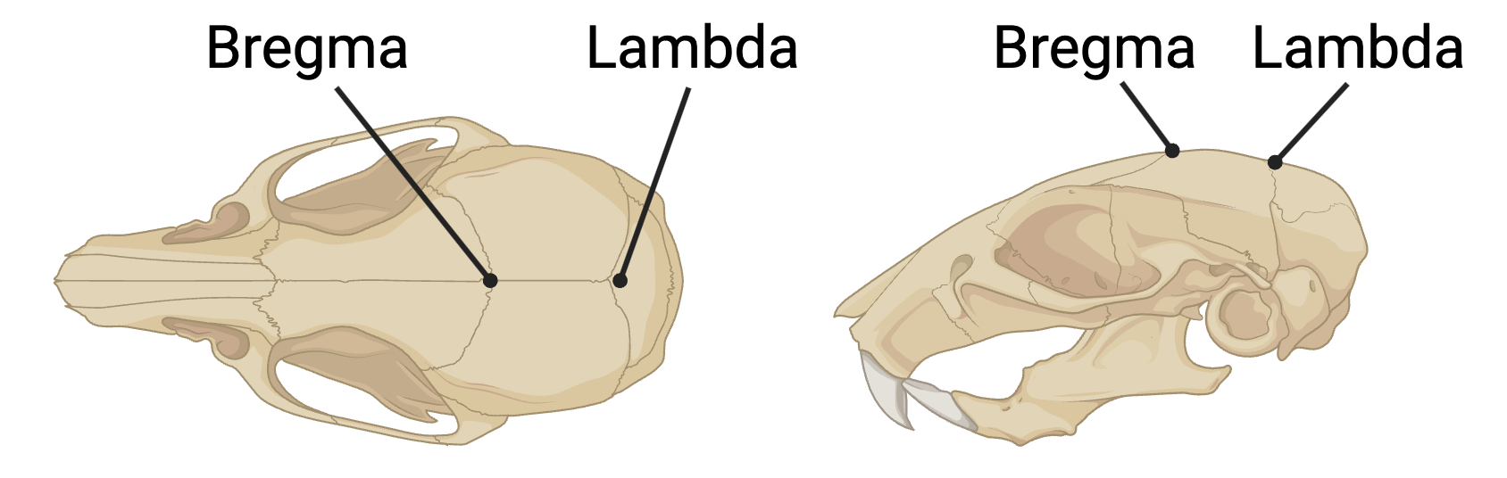
Bregma: the anatomical point on the skull at which the coronal suture (between frontal and parietal bones) is intersected perpendicularly by the sagittal suture (between left and right parietal bones).
Lambda: the meeting point of the sagittal suture (between left and right parietal bones) and the lambdoid suture (between parietal and occipital bones).
Both points serve as standard reference points for stereotaxic coordinates in neuroscience research.
Stereotaxic Coordinate System Conventions
Basic Coordinate System
All stereotaxic coordinate systems in BrainSTEM follow a right-handed coordinate system with the following conventions:
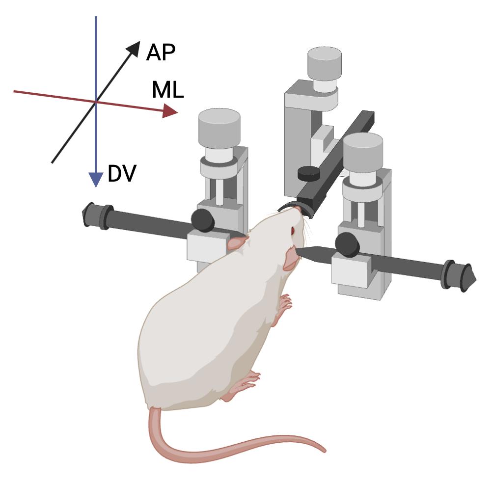
- AP (Anterior-Posterior) axis:
- Primary reference axis
- Positive values are anterior to reference point
- ML (Medial-Lateral) axis:
- Following right-hand rule relative to AP axis
- Positive values are to the right (as seen from behind)
- DV (Dorsal-Ventral) axis:
- Following right-hand rule
- Positive values are ventral
Landmark-referenced and spinal coordinates use the same signs (spinal coordinates measure RC, rostrocaudal, instead of AP). Standardized reference spaces keep their atlas’s own origin and axes, which are given with each space below.
Angle Measurement System
By default, angles are defined by three rotations, applied in this order:
- The AP angle, rotating clockwise around ML
- The ML angle, rotating clockwise around AP
- The rotation angle, rotating clockwise around the object’s depth axis
Proper understanding and application of these angles is critical for accurate probe placement and experimental reproducibility.
All stereotaxic measurements use three angles to specify orientation:
AP angle (Anterior-Posterior rotation):
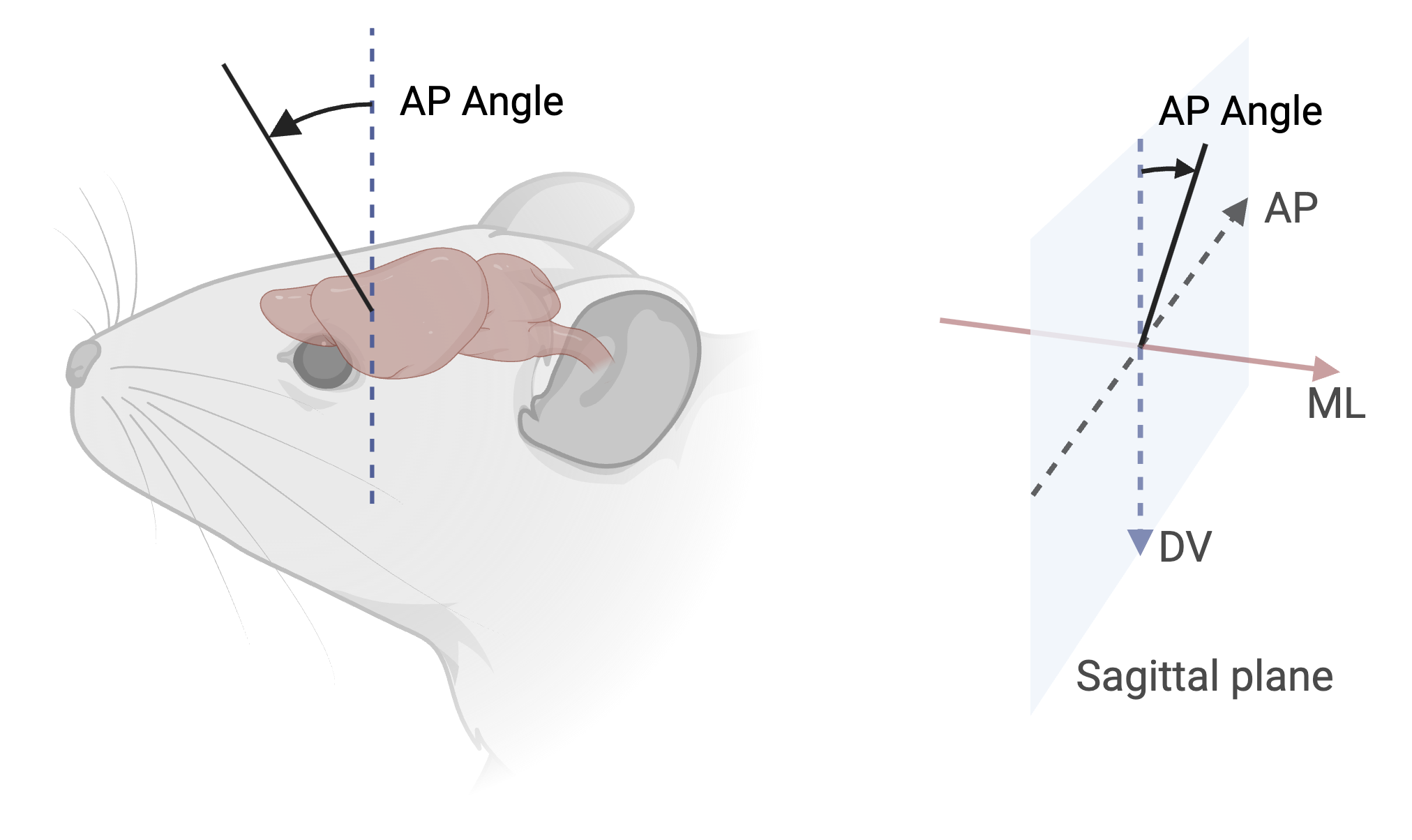
- Measured as rotation from the vertical axis in the sagittal plane
- 0° represents vertical along DV axis
- Range: -180° to +180°
- Positive values lean the top of the probe anteriorly, so its tip points posteriorly
- Example: +15° means the top of the probe leans 15° anterior of vertical
ML angle (Medial-Lateral rotation):
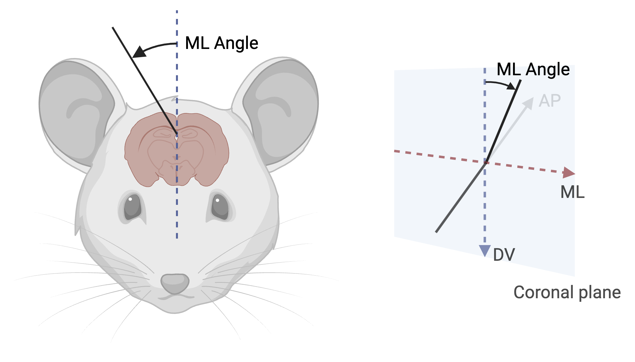
- Measured as rotation from the vertical axis in the coronal plane
- 0° represents vertical along DV axis
- Range: -180° to +180°
- Positive values lean the top of the probe to the right (as seen from behind), so its tip points to the left
- Example: +20° means the top of the probe leans 20° to the right of vertical
Rotation angle (around probe axis):
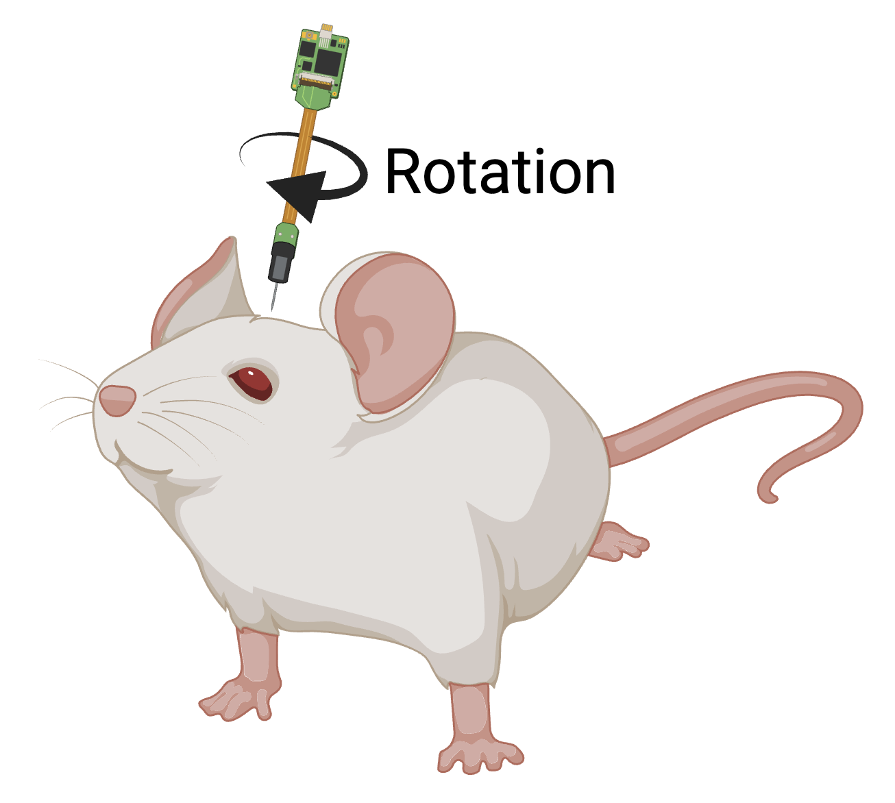
- 0° when probe features align with the coronal plane
- Range: -180° to +180°
- Positive rotation is clockwise when viewed from above
External coordinates
Positions in a frame the record itself defines, such as a rig, stage or manipulator frame, with the orientation given as Euler angles or a quaternion. Use them when no anatomical or atlas frame applies.
External XYZ Coordinates with Euler Orientation
Position in a declared external reference frame, such as a rig or stage frame, whose origin, axes, handedness and unrotated pose are defined in the record, with orientation as fixed-frame X, Y then Z rotations. Use it when no anatomical or atlas frame applies.
| Field | Description |
|---|---|
Reference frame name | Required. Text. Short name identifying the external coordinate frame used for this point. |
Reference frame description | Required. Text (multi-line). Define the frame origin, +X/+Y/+Z directions, handedness, and unrotated object pose. |
X coordinate | Quantity with unit. Physical X position in the declared external reference frame. Units: nm, µm, mm, m. |
X angle | Quantity with unit. First fixed-frame X rotation; positive is counter-clockwise viewed from +X toward origin. Units: °. |
Y coordinate | Quantity with unit. Physical Y position in the declared external reference frame. Units: nm, µm, mm, m. |
Y angle | Quantity with unit. Second fixed-frame Y rotation after X; positive is counter-clockwise viewed from +Y toward origin. Units: °. |
Z coordinate | Quantity with unit. Physical Z position in the declared external reference frame. Units: nm, µm, mm, m. |
Z angle | Quantity with unit. Third fixed-frame Z rotation after X then Y; positive is counter-clockwise viewed from +Z toward origin. Units: °. |
External XYZ Coordinates with Quaternion Orientation
Physical position and device orientation in a declared external reference frame. Quaternion values use the canonical Hamilton convention and rotate the declared device-local zero pose into the external frame.
| Field | Description |
|---|---|
Reference frame name | Required. Text. Short name identifying the external coordinate frame used for this pose. |
Reference frame description | Required. Text (multi-line). Define the origin, +X/+Y/+Z directions, handedness, and device-local zero pose. |
X coordinate | Quantity with unit. Physical X position in the declared external reference frame. Units: nm, µm, mm, m. |
Y coordinate | Quantity with unit. Physical Y position in the declared external reference frame. Units: nm, µm, mm, m. |
Z coordinate | Quantity with unit. Physical Z position in the declared external reference frame. Units: nm, µm, mm, m. |
Quaternion W | Required. Number. Scalar W component of the canonical unit Hamilton quaternion. Range: ≥ -1 and ≤ 1. |
Quaternion X | Required. Number. X vector component of the canonical unit Hamilton quaternion. Range: ≥ -1 and ≤ 1. |
Quaternion Y | Required. Number. Y vector component of the canonical unit Hamilton quaternion. Range: ≥ -1 and ≤ 1. |
Quaternion Z | Required. Number. Z vector component of the canonical unit Hamilton quaternion. Range: ≥ -1 and ≤ 1. |
Stereotaxic coordinates
Positions measured from Bregma or Lambda on a stereotaxic frame, either as absolute AP, ML and DV values or as a surface point with an insertion depth.
Stereotaxic Bregma-Based Absolute Coordinates
Absolute AP/ML/DV position measured from Bregma, with +AP anterior, +ML anatomical right and +DV ventral, plus AP and ML tilts and an axial rotation. Use it when DV is given from Bregma rather than as depth from the brain surface.
| Field | Description |
|---|---|
AP coordinate | Quantity with unit. Signed AP position of the absolute point from Bregma; positive is anterior. Units: nm, µm, mm, m. |
AP angle | Quantity with unit. First rotation: sagittal tilt from vertical around the ML axis; positive tilts anteriorly. Units: °. |
ML coordinate | Quantity with unit. Signed ML position of the absolute point from Bregma; positive is anatomical right. Units: nm, µm, mm, m. |
ML angle | Quantity with unit. Second rotation: coronal tilt from vertical around the AP axis, after the AP tilt; positive tilts to anatomical right. Units: °. |
DV coordinate | Quantity with unit. Signed DV position of the absolute point from Bregma; positive is ventral. Units: nm, µm, mm, m. |
Rotation | Quantity with unit. Clockwise rotation around the object’s depth axis when viewed from above; 0° aligns the major feature defined for the selected anchor type with the coronal plane. Units: °. |
Stereotaxic Bregma-Based Surface Coordinates with Depth
Insertion point given as AP/ML from Bregma (+AP anterior, +ML anatomical right) plus a non-negative depth along the final approach axis from brain-surface contact, not from the skull. Use it when depth is measured from where the device touches the brain.
| Field | Description |
|---|---|
AP coordinate | Quantity with unit. Signed AP position of the brain-surface insertion point from Bregma; positive is anterior. Units: nm, µm, mm, m. |
AP angle | Quantity with unit. First rotation: sagittal tilt from vertical around the ML axis; positive tilts anteriorly. Units: °. |
ML coordinate | Quantity with unit. Signed ML position of the brain-surface insertion point from Bregma; positive is anatomical right. Units: nm, µm, mm, m. |
ML angle | Quantity with unit. Second rotation: coronal tilt from vertical around the AP axis, after the AP tilt; positive tilts to anatomical right. Units: °. |
Depth | Quantity with unit. Non-negative insertion depth along the final depth axis from brain-surface contact at the insertion point, not from the skull surface. Units: nm, µm, mm, m. |
Rotation | Quantity with unit. Clockwise rotation around the object’s depth axis when viewed from above; 0° aligns the major feature defined for the selected anchor type with the coronal plane. Units: °. |
Stereotaxic Lambda-Based Absolute Coordinates
Absolute AP/ML/DV position measured from Lambda, with +AP anterior, +ML anatomical right and +DV ventral, plus AP and ML tilts and an axial rotation. Use it when DV is given from Lambda rather than as depth from the brain surface.
| Field | Description |
|---|---|
AP coordinate | Quantity with unit. Signed AP position of the absolute point from Lambda; positive is anterior. Units: nm, µm, mm, m. |
AP angle | Quantity with unit. First rotation: sagittal tilt from vertical around the ML axis; positive tilts anteriorly. Units: °. |
ML coordinate | Quantity with unit. Signed ML position of the absolute point from Lambda; positive is anatomical right. Units: nm, µm, mm, m. |
ML angle | Quantity with unit. Second rotation: coronal tilt from vertical around the AP axis, after the AP tilt; positive tilts to anatomical right. Units: °. |
DV coordinate | Quantity with unit. Signed DV position of the absolute point from Lambda; positive is ventral. Units: nm, µm, mm, m. |
Rotation | Quantity with unit. Clockwise rotation around the object’s depth axis when viewed from above; 0° aligns the major feature defined for the selected anchor type with the coronal plane. Units: °. |
Stereotaxic Lambda-Based Surface Coordinates with Depth
Insertion point given as AP/ML from Lambda (+AP anterior, +ML anatomical right) plus a non-negative depth along the final approach axis from brain-surface contact, not from the skull. Use it when depth is measured from where the device touches the brain.
| Field | Description |
|---|---|
AP coordinate | Quantity with unit. Signed AP position of the brain-surface insertion point from Lambda; positive is anterior. Units: nm, µm, mm, m. |
AP angle | Quantity with unit. First rotation: sagittal tilt from vertical around the ML axis; positive tilts anteriorly. Units: °. |
ML coordinate | Quantity with unit. Signed ML position of the brain-surface insertion point from Lambda; positive is anatomical right. Units: nm, µm, mm, m. |
ML angle | Quantity with unit. Second rotation: coronal tilt from vertical around the AP axis, after the AP tilt; positive tilts to anatomical right. Units: °. |
Depth | Quantity with unit. Non-negative insertion depth along the final depth axis from brain-surface contact at the insertion point, not from the skull surface. Units: nm, µm, mm, m. |
Rotation | Quantity with unit. Clockwise rotation around the object’s depth axis when viewed from above; 0° aligns the major feature defined for the selected anchor type with the coronal plane. Units: °. |
Landmark-referenced coordinates
Positions measured from a declared landmark other than Bregma or Lambda, such as the obex or the center of a cranial window, as absolute values or as a surface point with depth.
Landmark-Referenced AP/ML/DV Absolute Coordinates
Absolute AP/ML/DV position from a declared landmark that defines the zeros and axes, with +AP anterior, +ML right and +DV ventral, plus tilts and an axial rotation. Use it for landmarks other than Bregma and Lambda, such as the obex or a cranial window center.
| Field | Description |
|---|---|
Landmark reference | Choice. Landmark defining complete AP, ML, and DV zeros and axes for the absolute frame. Options: Obex, Interaural zero, Anterior commissure, Midcommissural point, Cranial window center, Surface landmark, Custom, Other. |
Landmark description | Text. Concise definition of the identity, 3-D origin, and AP/ML/DV axes of a surface, custom, or other landmark. |
AP coordinate | Quantity with unit. AP position of the absolute point from the frame origin; positive is anterior. Units: nm, µm, mm, m. |
ML coordinate | Quantity with unit. ML position of the absolute point from the frame origin; positive is anatomical right. Units: nm, µm, mm, m. |
DV coordinate | Quantity with unit. DV position of the absolute point from the frame origin; positive is ventral. Units: nm, µm, mm, m. |
AP angle | Quantity with unit. First rotation: sagittal tilt from vertical around the ML axis; positive tilts anteriorly. Units: °. |
ML angle | Quantity with unit. Second rotation: coronal tilt from vertical around the AP axis, after the AP tilt; positive tilts to anatomical right. Units: °. |
Rotation | Quantity with unit. Clockwise rotation around the object’s depth axis when viewed from above; 0° aligns the major feature defined for the selected anchor type with the coronal plane. Units: °. |
Landmark-Referenced AP/ML Surface Coordinates with Depth
Insertion point given as AP/ML from a declared landmark (+AP anterior, +ML anatomical right) plus a non-negative insertion depth along the final approach axis from a declared surface. Use it for landmark-referenced insertions where depth is measured from the contacted surface.
| Field | Description |
|---|---|
Landmark reference | Choice. Landmark defining AP and ML zeros and axes for the insertion-point frame. Options: Obex, Interaural zero, Anterior commissure, Midcommissural point, Cranial window center, Surface landmark, Custom, Other. |
Landmark description | Text. Concise definition of the identity, origin, and AP/ML axes of a surface, custom, or other landmark. |
Insertion-depth reference surface | Choice. Physical interface at the insertion point from which insertion depth begins. Options: Skull surface, Dura surface, Pia surface, Brain surface, Brainstem surface, Cord surface, Custom. |
Surface reference description | Text. Concise physical definition of the custom surface used as insertion-depth zero. |
AP coordinate | Quantity with unit. AP position of the surface insertion point from the landmark; positive is anterior. Units: nm, µm, mm, m. |
ML coordinate | Quantity with unit. ML position of the surface insertion point from the landmark; positive is anatomical right. Units: nm, µm, mm, m. |
Insertion depth | Quantity with unit. Non-negative insertion depth along the final depth axis from contact with the selected surface at the insertion point. Units: nm, µm, mm, m. |
AP angle | Quantity with unit. First rotation: sagittal tilt from vertical around the ML axis; positive tilts anteriorly. Units: °. |
ML angle | Quantity with unit. Second rotation: coronal tilt from vertical around the AP axis, after the AP tilt; positive tilts to anatomical right. Units: °. |
Rotation | Quantity with unit. Clockwise rotation around the object’s depth axis when viewed from above; 0° aligns the major feature defined for the selected anchor type with the coronal plane. Units: °. |
Spinal coordinates
Positions along the spinal cord given as rostrocaudal, mediolateral and dorsoventral values from a declared vertebral or segmental landmark, as absolute values or as a surface point with depth.
Spinal RC/ML/DV Absolute Coordinates
Absolute spinal position from an origin on the cord central axis at a declared segment or vertebral level, with +RC rostral along the cord centerline, +ML right of midline and +DV ventral, plus RC and ML tilts and an axial rotation.
| Field | Description |
|---|---|
Reference mode | Choice. The anatomical convention anchoring the frame; vertebral references project onto the cord central axis. Options: Spinal segment, Vertebral level, Custom. |
Reference level | Text. The spinal segment or vertebral level containing the rostrocaudal origin. |
Reference feature | Choice. The feature fixing the frame origin: the point on the cord central axis at this rostrocaudal position. Options: Rostral boundary, Center, Caudal boundary, Interlevel junction, Observed landmark, Custom. |
Reference description | Text. A concise physical definition of the custom or observed reference point in all three axes. |
RC coordinate | Quantity with unit. Rostral-positive position from the declared origin along the local cord centerline. Units: nm, µm, mm, m. |
RC angle | Quantity with unit. First approach rotation around ML; 0° follows the depth axis and positive tilts rostrally. Units: °. |
ML coordinate | Quantity with unit. Right-positive position from the spinal cord midline. Units: nm, µm, mm, m. |
ML angle | Quantity with unit. Second approach rotation around RC after RC tilt; positive tilts to anatomical right. Units: °. |
DV coordinate | Quantity with unit. Ventral-positive absolute position from the cord central axis at the declared origin. Units: nm, µm, mm, m. |
Rotation | Quantity with unit. Clockwise rotation around the object’s depth axis when viewed from above; 0° aligns the major feature defined for the selected anchor type with the coronal plane. Units: °. |
Spinal RC/ML Surface Coordinates with Depth
Spinal insertion point given as RC/ML from a declared segment or vertebral reference (+RC rostral, +ML right of midline) plus a non-negative insertion depth from a declared surface. Use it for spinal injections or electrode insertions with depth measured from the contacted surface.
| Field | Description |
|---|---|
Reference mode | Choice. The anatomical convention used to anchor the spinal frame. Options: Spinal segment, Vertebral level, Custom. |
Reference level | Text. The spinal segment or vertebral level containing the rostrocaudal origin. |
Reference feature | Choice. The exact feature within or between levels that defines rostrocaudal zero. Options: Rostral boundary, Center, Caudal boundary, Interlevel junction, Observed landmark, Custom. |
Reference description | Text. A concise physical definition of a custom or observed spinal reference. |
Depth reference surface | Choice. Physical interface at the insertion point from which insertion depth begins. Options: Dura surface, Pia surface, Cord surface, Custom. |
Surface reference description | Text. A concise physical definition of a custom depth-reference surface. |
RC insertion coordinate | Quantity with unit. Rostral-positive insertion-point position from the declared origin along the local cord centerline. Units: nm, µm, mm, m. |
RC angle | Quantity with unit. First approach rotation around ML; 0° follows the depth axis and positive tilts rostrally. Units: °. |
ML insertion coordinate | Quantity with unit. Right-positive insertion-point position from the spinal cord midline. Units: nm, µm, mm, m. |
ML angle | Quantity with unit. Second approach rotation around RC after RC tilt; positive tilts to anatomical right. Units: °. |
Insertion depth | Quantity with unit. Non-negative insertion depth along the final depth axis from contact with the selected surface at the insertion point. Units: nm, µm, mm, m. |
Rotation | Quantity with unit. Clockwise rotation around the object’s depth axis when viewed from above; 0° aligns the major feature defined for the selected anchor type with the coronal plane. Units: °. |
Standardized reference spaces
Positions in a published atlas space, such as the Allen CCFv3, Waxholm or MNI152 templates, measured from the atlas origin with its own axis conventions. Use them for targets planned in or registered to an atlas.
Brain/MINDS Marmoset Atlas 2.0 XYZ Absolute Coordinates
Absolute position in Brain/MINDS Marmoset Atlas 2.0 space, measured from the atlas origin between the commissures (not ear bar zero), with +X anatomical right, +Y anterior and +Z superior, plus AP and ML tilts and an axial roll. Use it for marmoset targets.
| Field | Description |
|---|---|
X coordinate | Quantity with unit. Physical distance from the BMA 2.0 atlas origin (between the commissures, not ear bar zero); positive X is anatomical right. Units: nm, µm, mm, m. |
Y coordinate | Quantity with unit. Physical distance from the BMA 2.0 atlas origin (between the commissures, not ear bar zero); positive Y is anterior. Units: nm, µm, mm, m. |
Z coordinate | Quantity with unit. Physical distance from the BMA 2.0 atlas origin (between the commissures, not ear bar zero); positive Z is superior. Units: nm, µm, mm, m. |
AP angle | Quantity with unit. First tilt from inferior vertical; positive tilts anteriorly. Units: °. |
ML angle | Quantity with unit. Second tilt after the AP tilt; positive tilts to anatomical right. Units: °. |
Rotation | Quantity with unit. Final axial roll around the placed object’s approach axis. Units: °. |
Allen Mouse CCFv3 XYZ Absolute Coordinates
Absolute position in Allen Mouse CCFv3 space, measured from the anterior-superior-left origin with +X posterior, +Y ventral and +Z right, plus two tilts and an axial roll. Use it for mouse targets planned in or registered to the Allen atlas.
| Field | Description |
|---|---|
X coordinate | Quantity with unit. Physical distance from the CCFv3 anterior-superior-left origin; positive X is posterior. Units: nm, µm, mm, m. |
X angle | Quantity with unit. First tilt from +Y in the X-Y sagittal plane; positive tilts toward anterior (-X). Units: °. |
Y coordinate | Quantity with unit. Physical distance from the CCFv3 anterior-superior-left origin; positive Y is inferior or ventral. Units: nm, µm, mm, m. |
Z coordinate | Quantity with unit. Physical distance from the CCFv3 anterior-superior-left origin; positive Z is rightward. Units: nm, µm, mm, m. |
Z angle | Quantity with unit. Second tilt in the Y-Z coronal plane after X tilt; positive tilts toward right (+Z). Units: °. |
Rotation | Quantity with unit. Final axial roll: clockwise from above; 0° aligns the anchor type’s major feature with coronal plane. Units: °. |
JRC2018 Unisex Fly Brain XYZ Absolute Coordinates
Absolute position in the JRC2018 Unisex Drosophila brain template, measured from the volume corner with +X toward the fly’s left, +Y ventral and +Z posterior (anterior-view stack convention), plus two tilts and an axial roll. Use it for fly brain targets.
| Field | Description |
|---|---|
X coordinate | Quantity with unit. Physical distance from the JRC2018U volume corner; positive X is toward the fly’s left. Units: nm, µm, mm, m. |
Y coordinate | Quantity with unit. Physical distance from the JRC2018U volume corner; positive Y is ventral per the anterior-view stack convention. Units: nm, µm, mm, m. |
Z coordinate | Quantity with unit. Physical distance from the JRC2018U volume corner; positive Z is posterior per the anterior-view stack convention. Units: nm, µm, mm, m. |
Z angle | Quantity with unit. First tilt from ventral vertical in the Y-Z sagittal plane; positive tilts toward anterior (-Z). Units: °. |
X angle | Quantity with unit. Second tilt in the X-Y coronal plane after the Z tilt; positive tilts toward the fly’s right (-X). Units: °. |
Rotation | Quantity with unit. Final axial roll around the placed object’s approach axis. Units: °. |
MNI152 ICBM 2009c Human XYZ Absolute Coordinates
Absolute position in MNI152 ICBM 2009c human template space, measured from the anterior-commissure origin with +X anatomical right, +Y anterior and +Z superior, plus AP and ML tilts and an axial roll. Use it for human targets in MNI space.
| Field | Description |
|---|---|
X coordinate | Quantity with unit. Physical distance from the MNI anterior-commissure origin; positive X is anatomical right. Units: nm, µm, mm, m. |
Y coordinate | Quantity with unit. Physical distance from the MNI anterior-commissure origin; positive Y is anterior. Units: nm, µm, mm, m. |
Z coordinate | Quantity with unit. Physical distance from the MNI anterior-commissure origin; positive Z is superior. Units: nm, µm, mm, m. |
AP angle | Quantity with unit. First tilt from inferior vertical; positive tilts anteriorly. Units: °. |
ML angle | Quantity with unit. Second tilt after the AP tilt; positive tilts to anatomical right. Units: °. |
Rotation | Quantity with unit. Final axial roll around the placed object’s approach axis. Units: °. |
mapzebrain Larval Zebrafish XYZ Absolute Coordinates
Absolute position in the mapzebrain larval zebrafish atlas, measured from the volume corner with +X anatomical right, +Y posterior and +Z superior, plus two tilts and an axial roll. Use it for larval zebrafish brain targets.
| Field | Description |
|---|---|
X coordinate | Quantity with unit. Physical distance from the mapzebrain volume corner; positive X is anatomical right. Units: nm, µm, mm, m. |
Y coordinate | Quantity with unit. Physical distance from the mapzebrain volume corner; positive Y is posterior. Units: nm, µm, mm, m. |
Z coordinate | Quantity with unit. Physical distance from the mapzebrain volume corner; positive Z is superior per the BrainGlobe source-orientation record. Units: nm, µm, mm, m. |
Y angle | Quantity with unit. First tilt from inferior vertical in the Y-Z sagittal plane; positive tilts toward anterior (-Y). Units: °. |
X angle | Quantity with unit. Second tilt in the X-Z coronal plane after the Y tilt; positive tilts toward right (+X). Units: °. |
Rotation | Quantity with unit. Final axial roll around the placed object’s approach axis. Units: °. |
NIMH Macaque Template v2 XYZ Absolute Coordinates
Absolute position in NIMH Macaque Template v2 space, measured from ear bar zero with +X anatomical right, +Y anterior and +Z superior, plus AP and ML tilts and an axial roll. Use it for macaque targets in NMT v2.
| Field | Description |
|---|---|
X coordinate | Quantity with unit. Physical distance from ear bar zero; positive X is anatomical right. Units: nm, µm, mm, m. |
Y coordinate | Quantity with unit. Physical distance from ear bar zero; positive Y is anterior. Units: nm, µm, mm, m. |
Z coordinate | Quantity with unit. Physical distance from ear bar zero; positive Z is superior. Units: nm, µm, mm, m. |
AP angle | Quantity with unit. First tilt from inferior vertical; positive tilts anteriorly. Units: °. |
ML angle | Quantity with unit. Second tilt after the AP tilt; positive tilts to anatomical right. Units: °. |
Rotation | Quantity with unit. Final axial roll around the placed object’s approach axis. Units: °. |
Waxholm Space Rat Brain Atlas v4 XYZ Absolute Coordinates
Absolute position in Waxholm Space rat brain atlas v4, measured from the WHS origin with +X anatomical right, +Y anterior and +Z superior, plus AP and ML tilts and an axial roll. Use it for rat targets in WHS space.
| Field | Description |
|---|---|
X coordinate | Quantity with unit. Physical distance from the WHS origin; positive X is anatomical right. Units: nm, µm, mm, m. |
Y coordinate | Quantity with unit. Physical distance from the WHS origin; positive Y is anterior. Units: nm, µm, mm, m. |
Z coordinate | Quantity with unit. Physical distance from the WHS origin; positive Z is superior. Units: nm, µm, mm, m. |
AP angle | Quantity with unit. First tilt from inferior vertical; positive tilts anteriorly. Units: °. |
ML angle | Quantity with unit. Second tilt after the AP tilt; positive tilts to anatomical right. Units: °. |
Rotation | Quantity with unit. Final axial roll around the placed object’s approach axis. Units: °. |
Specimen coordinates
Positions on or inside an ex-vivo specimen, given in a frame attached to the specimen itself, as surface XY values with or without depth or as volume XYZ values.
Specimen Surface XY Coordinates
Two-dimensional position on a specimen surface, with a declared origin, a mapping of specimen directions to +X and +Y and a clockwise in-plane rotation. Use it for surface locations on ex-vivo specimens, such as slices or whole mounts, where depth is not needed.
| Field | Description |
|---|---|
Origin | Choice. Origin convention for the specimen-surface XY frame. Options: Center, Top left, Top right, Bottom left, Bottom right, Landmark, Embedding block origin, Custom. |
Origin description | Text. Define the physical point and axes for a landmark or custom origin. |
Specimen orientation | Text. Map specimen anatomical or preparation directions to positive X and Y. |
X coordinate | Quantity with unit. Physical X position on the declared specimen surface. Units: nm, µm, mm, m. |
Y coordinate | Quantity with unit. Physical Y position on the declared specimen surface. Units: nm, µm, mm, m. |
In-plane rotation | Quantity with unit. Clockwise viewed toward the surface; 0° aligns the anchor major feature with +Y. Units: °. |
Specimen Surface XY Coordinates with Depth
Insertion point on a specimen surface, given as X/Y from a declared origin, plus insertion depth from a declared surface and an axial rotation. Use it for electrodes or pipettes entering an ex-vivo specimen from its surface.
| Field | Description |
|---|---|
XY origin | Choice. Origin convention for the specimen-surface XY frame. Options: Center, Top left, Top right, Bottom left, Bottom right, Landmark, Embedding block origin, Custom. |
XY origin description | Text. Define the physical point and axes for a landmark or custom origin. |
Specimen orientation | Text. Map specimen anatomical or preparation directions to positive X and Y. |
Insertion-depth reference surface | Choice. Physical interface at the insertion point where insertion depth begins. Options: Exposed specimen surface, Cut face, Slice surface, Pia surface, Coverslip surface, Custom. |
Surface reference description | Text. For a custom surface, define the physical interface used as insertion-depth zero. |
X insertion coordinate | Quantity with unit. Physical X position of the specimen-surface insertion point. Units: nm, µm, mm, m. |
Y insertion coordinate | Quantity with unit. Physical Y position of the specimen-surface insertion point. Units: nm, µm, mm, m. |
Insertion depth | Quantity with unit. Insertion distance along the final depth axis from the selected surface at entry. Units: nm, µm, mm, m. |
Axial rotation | Quantity with unit. Clockwise about final depth axis from above; 0° aligns the anchor major feature with +Y. Units: °. |
Specimen Volume XYZ Coordinates
Three-dimensional position within a specimen, with a declared origin, a mapping of specimen directions to +X, +Y and +Z, and orientation as fixed-frame X, Y then Z rotations. Use it for locations inside cleared tissue, explants or other volumetric specimens.
| Field | Description |
|---|---|
Origin | Choice. Origin convention for the specimen-volume XYZ frame. Options: Center, Rostral dorsal left corner, Embedding block origin, Landmark, Custom. |
Origin description | Text. Define the physical point and axes for a landmark or custom origin. |
Specimen orientation | Text. Map specimen directions to +X/+Y/+Z; with the anchor major feature, this defines zero pose. |
X coordinate | Quantity with unit. Physical X position in the declared specimen-volume frame. Units: nm, µm, mm, m. |
Y coordinate | Quantity with unit. Physical Y position in the declared specimen-volume frame. Units: nm, µm, mm, m. |
Z coordinate | Quantity with unit. Physical Z position in the declared specimen-volume frame. Units: nm, µm, mm, m. |
X angle | Quantity with unit. First fixed-frame X rotation from zero; positive is counter-clockwise viewed from +X toward origin. Units: °. |
Y angle | Quantity with unit. Second fixed-frame Y rotation after X; positive is counter-clockwise viewed from +Y toward origin. Units: °. |
Z angle | Quantity with unit. Third fixed-frame Z rotation after X then Y; positive is counter-clockwise viewed from +Z toward origin. Units: °. |
Container coordinates
Positions relative to the labware holding a specimen, either a well of a gridded plate or an XYZ frame attached to the container.
Container Grid Well Coordinates
Location in a multiwell plate or gridded container, given as a well ID (A1 top-left, rows increasing back or down, columns increasing right) and an X/Y offset from the well center. Use it for specimens held in labware wells.
| Field | Description |
|---|---|
Well | Text. Well ID such as A1: A1 is top-left; rows increase back/down and columns increase right. |
X offset from well center | Quantity with unit. Physical offset from well center; positive X is right in the labware view. Units: nm, µm, mm, m. |
Y offset from well center | Quantity with unit. Physical offset from well center; positive Y is back/down in the labware view. Units: nm, µm, mm, m. |
Container-Local XYZ Coordinates
Position in an XYZ frame attached to a container, with a declared origin and a mapping of container +X, +Y and +Z to the preparation or setup. Use it when a location is best given relative to the container rather than the specimen.
| Field | Description |
|---|---|
Origin | Choice. Origin convention for the container-local XYZ frame. Options: Center, Dish center, Insert center, Well center, Custom. |
Origin description | Text. Define the physical point and axes for a custom container origin. |
Container orientation | Text. Map container-local positive X, Y, and Z to the preparation or setup. |
X coordinate | Quantity with unit. Physical X position in the declared container-local frame. Units: nm, µm, mm, m. |
Y coordinate | Quantity with unit. Physical Y position in the declared container-local frame. Units: nm, µm, mm, m. |
Z coordinate | Quantity with unit. Physical Z position in the declared container-local frame. Units: nm, µm, mm, m. |
API access
The same types are documented for API users, with property codes, versions and payload examples, on the Coordinates schemas API page.